7 Best Flow Valves for Industrial Applications
Industrial plants rely on controlled movement of water, steam, oil, gas, and process chemicals. The right flow valves help regulate that movement, isolate equipment, or prevent reverse flow. The wrong choice can cause pressure loss, leakage, sluggish control, or unnecessary maintenance. Small details matter.
This guide introduces seven widely used valve types: ball, gate, globe, butterfly, check, diaphragm, and needle valves. Each design handles flow differently. Ball valves open quickly, while globe valves support more gradual throttling. Check valves act automatically, but they still need suitable flow conditions and installation orientation. These are practical distinctions, not universal promises.
Choosing among them means checking the fluid, operating pressure, temperature, pipe size, and required flow rate. Material compatibility matters, especially when a process fluid may corrode or wear valve surfaces. Actuation method and access for maintenance also affect daily performance. A valve that looks suitable on a specification sheet may be awkward to reach behind a pump or beside a hot pipe. That is easy to overlook.
This overview compares typical strengths, limitations, and industrial uses without treating one design as best for every system. Actual results depend on operating conditions, installation, and maintenance. The comparison is useful, but imperfect; plant-specific engineering review remains important.
Understanding the Role of Flow Valves in Industrial Systems
Flow valves do more than open or close a pipe. They regulate rate, pressure, and direction, helping equipment operate within safe process limits. In a steam line, for example, a valve that responds slowly can cause pressure swings and uneven heating. In a water circuit, poor control may leave some equipment starved while other branches receive excess flow.
The U.S. Department of Energy’s Improving Pumping System Performance: A Sourcebook for Industry reports that pumping systems use nearly 20% of global electricity, and 25–50% of energy in some industrial operations. A valve that throttles flow unnecessarily can add resistance and increase pump workload. The International Energy Agency’s Energy Efficiency 2023 reports that industry accounted for about 37% of global final energy consumption in 2022. Small changes matter. Correct sizing and placement can help control energy losses, but actual results depend on operating conditions and maintenance.
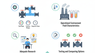
In practice, valve selection should consider fluid type, temperature, pressure range, required response, and service access. Operators should verify performance during commissioning, then compare readings with normal process conditions. A catalog rating alone is not enough. Plant teams sometimes choose a valve under schedule pressure and revisit the decision only after control problems appear; that habit deserves scrutiny. Regular checks for sticking, leakage, and unusual pressure drops can reveal trouble early.
How Flow Valves Regulate Pressure, Direction, and Flow Rate
Industrial flow valves do more than open or close a pipe. They shape pressure, route fluid, and meter flow as operating conditions change. A globe valve can trim flow through a narrow seat; a butterfly valve provides compact isolation and throttling. Check valves prevent reverse flow, while directional valves shift fluid between branches. The choice depends on the fluid, temperature, pressure drop, and response time—not just pipe diameter. At a pump discharge, an undersized valve can create excess resistance and heat. Small details matter.
The U.S. Department of Energy’s Improving Pumping System Performance: A Sourcebook for Industry reports that
pumping systems account for nearly 20% of global electricity demand and 25–50% of energy use in some industrial operations.
This describes pumping systems, not valves alone, but it shows why valve losses deserve attention. Pressure-control valves stabilize downstream conditions; flow-control valves regulate a target rate; directional valves send fluid to the required circuit. Compare flow coefficient, allowable pressure drop, and control range against measured demand. Calculations can still miss how a valve behaves when loads fluctuate. Check operation at startup and partial load, and record pressure on both sides of the valve.
Seven Common Flow Valve Types and Their Industrial Uses
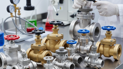
Industrial flow valves control, isolate, or redirect fluids across process lines.
Gate valves suit full-open or full-closed service, such as isolating a maintenance branch. They are poor choices for routine throttling because partly open discs may wear.
Globe valves provide steadier flow adjustment, often on cooling-water or steam lines.
Ball valves open quickly with a quarter turn and provide tight shutoff. Simple, but not foolproof.
Butterfly valves are compact and lightweight, making them useful on large-diameter water and air lines.
Plug valves also turn quickly and can handle some slurry services, though deposits may affect operation.
Check valves close automatically when flow reverses, helping protect pumps from backflow.
Needle valves allow fine adjustment in small-bore instrument lines.
Each type has limits; pressure, temperature, fluid chemistry, and expected cycling all matter.
Tips: Match the valve body and seal materials to the actual fluid and operating temperature. Check the pressure rating, flow direction, and actuator needs before installation. A common oversight is sizing by pipe diameter alone; flow rate and pressure drop matter too. Verify the choice against equipment data, and reassess it when service conditions change.
Selecting and Maintaining Flow Valves for Reliable Operation
Choosing a flow valve starts with the process, not the catalog. Record the fluid, operating temperature, pressure range, and expected flow before comparing designs. A valve sized only for peak demand may operate nearly closed during normal use, making control unstable. For water lines, note suspended solids and corrosion risks; for hot service, verify body and seal temperature limits. Small details matter.
Match the valve’s function to the job. Control valves regulate flow, while isolation valves are designed to stop it; one type may not perform both tasks well. Check the pressure drop across the valve, since excessive drop can cause noise, vibration, or cavitation. Confirm that wetted materials suit the fluid, and consider how operators will reach the valve for adjustment. A handwheel is not a substitute for correct sizing.
Reliable operation depends on routine checks, not just installation quality. Follow site isolation and depressurization procedures before inspection. Look for leakage around the stem, damaged seals, unusual vibration, and deposits that restrict movement. Compare operating readings with the commissioning record, and document adjustments so recurring changes are visible. Clean upstream strainers when the process allows. Even careful plans miss things; a small leak can be easy to dismiss until it affects nearby equipment.