
How to Choose a Pneumatic Pressure Control Valve in 2026?
Choosing a pneumatic pressure control valve in 2026 requires more than matching a pressure range. In a real plant, air quality, cycling speed, temperature, and downstream demand can change performance within minutes. A valve that looks suitable on paper may hunt, leak, or respond slowly beside a vibrating compressor. Selection should begin with measured operating conditions, not a catalog image.
This guide explains how engineers can compare valve types, control accuracy, flow capacity, materials, connection sizes, and maintenance needs. It also considers proportional control, feedback signals, fail-safe behavior, and compatibility with existing PLC systems. Practical checks matter. Record inlet pressure during peak demand, inspect the filter-regulator-lubricator assembly, and confirm whether the actuator needs clean, dry air. Small details matter.
Reliable decisions depend on evidence. Review manufacturer datasheets, pressure-drop curves, test results, certification information, and installation instructions. Confirm the proposed pneumatic pressure control valve under normal and worst-case conditions. A workshop trial or supervised commissioning test can reveal noise, unstable output, or awkward adjustment access before production suffers. Yet no checklist is perfect. Technically correct selections can fail because operators cannot read the gauge or replacement seals are unavailable. This article treats cost as only one factor. It focuses on safe performance, repeatable control, service support, and honest comparison, helping readers choose equipment that remains dependable beyond the first installation.
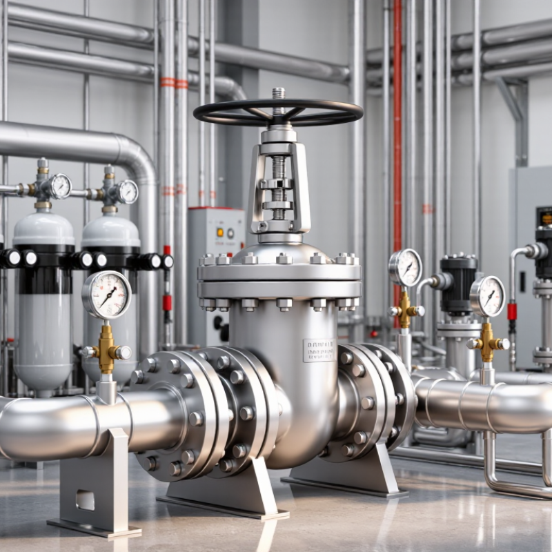
What Is a Pneumatic Pressure Control Valve?
How to Choose a Pneumatic Pressure Control Valve in 2026?
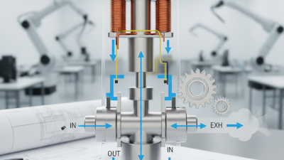
A pneumatic pressure control valve uses compressed air to move an actuator and regulate process pressure. Unlike a simple manual regulator, it can respond continuously to a pressure signal. A sensing element measures downstream pressure. The controller then adjusts valve position, correcting flow changes, demand spikes, or unstable supply conditions. The loop is simple in theory. Real plants are less forgiving.
Start with the required inlet, outlet, and differential pressures. Confirm flow rate at minimum, normal, and maximum demand. ISA-75.01.01 provides recognized equations for control-valve sizing, including flow coefficient calculations. Oversizing is common. It can cause hunting, noise, and poor low-flow control. Select the correct fail-open or fail-closed action after reviewing the process risk. A spring-return actuator may react faster, but it needs adequate instrument-air pressure.
Compressed air quality also matters. ISO 8573-1 classifies particles, water, and oil in compressed air. Contamination can damage positioners and slow actuator movement. The U.S. Department of Energy reports that leaks may waste 20–30% of compressed-air output in poorly maintained systems. That figure is a warning, not a universal result. Actual losses depend on pressure, pipe condition, and maintenance. In 2026, digital diagnostics can expose valve stiction and response delays, but sensors still need calibration. A technically correct valve can fail in practice when tuning, air quality, or installation details are overlooked.
How to Choose a Pneumatic Pressure Control Valve in 2026? - What Is a Pneumatic Pressure Control Valve?
| Selection dimension | What it means | Common options or typical values | Recommended decision rule |
|---|---|---|---|
| Basic definition | A pneumatic pressure control valve regulates compressed-air pressure by changing the flow area in response to a pressure signal, spring force, pilot signal, or electronic command. | Pressure-reducing, back-pressure, relief, sequence, proportional, and electro-pneumatic control valves. | Define whether the valve must reduce downstream pressure, maintain upstream pressure, protect against overpressure, or continuously modulate pressure. |
| Control function | The primary behavior expected from the valve in the pneumatic circuit. | Reduce pressure; maintain back pressure; vent excess pressure; switch at a set pressure; or regulate proportionally. | Use a reducing regulator for a lower, stable outlet pressure; use a relief valve for overpressure protection; use a proportional valve when variable electronic control is required. |
| Inlet pressure | The highest, lowest, and normal pressure entering the valve. | Typical industrial pneumatic systems operate around 6 bar or 87 psi, but actual inlet limits depend on the valve design. | Select a valve whose maximum allowable inlet pressure exceeds the highest possible supply pressure, including regulator failure or pressure spikes. |
| Required outlet pressure | The pressure that must be maintained at the downstream equipment or process. | Common machine-air settings include approximately 2–6 bar, or 29–87 psi; exact requirements vary by actuator and process. | Choose a pressure range that places the normal set point near the middle of the adjustment range for better control resolution. |
| Flow rate | The air volume the valve must pass while maintaining the required pressure. | Specified by the manufacturer using standard or normal liters per minute, such as L/min, NL/min, or SCFM. | Size for the maximum continuous and peak demand. Avoid selecting only from pipe size; pressure drop and valve flow capacity are also critical. |
| Pressure drop | The difference between inlet and outlet pressure while air is flowing. | A valve may show a higher outlet pressure at low flow and a lower outlet pressure at high flow, known as droop. | Review flow curves at the actual inlet pressure and set point. Select adequate capacity instead of relying only on nominal port diameter. |
| Valve type | The mechanical and control arrangement used to regulate pressure. | Direct-acting regulator; pilot-operated regulator; relieving regulator; non-relieving regulator; proportional valve; safety relief valve. | Use direct-acting designs for simple, compact applications. Consider pilot-operated or proportional designs for higher flow, tighter regulation, or automated control. |
| Adjustment method | How the set pressure is changed and secured. | Manual knob, screw adjustment, lockable adjustment, pneumatic pilot, or electrical command. | Choose a lockable or tamper-resistant adjustment where unauthorized changes could affect safety, quality, or machine performance. |
| Response and accuracy | How quickly and precisely the valve responds to changes in supply pressure, demand, or command. | Static regulation, dynamic regulation, hysteresis, repeatability, sensitivity, and response time are commonly specified. | For fast, changing loads, compare dynamic test data rather than relying only on the stated adjustment range. |
| Port size and connection | The inlet and outlet connection standard and nominal size. | Threaded, push-in, compression, flange, or manifold connections; metric and inch thread standards are common. | Match the connection standard, available installation space, tubing size, and required flow. Do not force incompatible threads. |
| Air quality | The amount of particulate, water, oil, and other contamination in the compressed air. | General industrial air; filtered air; dry air; oil-free air; cleanroom or process air. | Install filtration and water separation as required. Verify the valve's contamination tolerance and compatibility with lubricated or non-lubricated service. |
| Temperature range | The allowable ambient and media temperature range for reliable operation. | Many general-purpose valves are rated for approximately 0–60 °C, but ratings vary by seals, materials, and configuration. | Use the actual minimum and maximum temperatures, including cold start, heat from nearby equipment, and compressed-air expansion. |
| Materials and sealing | The wetted and structural materials that determine durability and compatibility. | Aluminum, brass, stainless steel, engineering polymers, and elastomer seals such as nitrile, EPDM, or fluorocarbon. | Check compatibility with moisture, cleaning agents, ambient chemicals, oxygen service, and any process gas before ordering. |
| Relieving capability | Whether trapped downstream pressure can be vented when the set point is reduced. | Relieving regulators exhaust downstream air; non-relieving regulators do not intentionally vent it. | Select a relieving design only when exhaust is acceptable and safe. Use non-relieving designs where venting is undesirable or prohibited. |
| Fail-safe behavior | The valve's response to loss of electrical power, pilot air, or control signal. | Fail-open, fail-closed, hold position, or controlled venting, depending on the design. | Perform a documented risk assessment and select the failure position that leaves personnel, equipment, and product in the safest condition. |
| Instrumentation and feedback | The method used to measure or communicate actual pressure. | Mechanical gauge, pressure switch, pressure transducer, analog signal, or digital communication interface. | Use a gauge for local adjustment and a transducer or switch when monitoring, alarms, closed-loop control, or data logging is required. |
| Installation position | The physical orientation and accessibility of the valve in the system. | Inline, panel-mounted, manifold-mounted, or compact integrated assemblies. | Allow access for adjustment, drainage, inspection, and replacement. Follow the flow arrow and the manufacturer's mounting instructions. |
| Noise and exhaust | Sound generated by throttling or by exhausting air to atmosphere. | Noise depends on pressure ratio, flow, valve geometry, exhaust frequency, and the use of silencers. | Check measured sound data where operators are nearby. Route exhaust safely and use a suitable silencer without restricting required flow. |
| Safety and compliance | The legal, functional, and application-specific requirements governing the installation. | Pressure-equipment requirements, machinery safety, electrical protection, clean-service rules, and site-specific codes. | Confirm applicable local regulations and required documentation. A pressure regulator is not automatically a substitute for a certified safety relief device. |
| Maintenance requirements | The inspection, cleaning, calibration, and replacement work needed during service. | Periodic leak checks, filter servicing, set-point verification, seal replacement, and gauge or sensor calibration. | Choose a serviceable design with available replacement parts and clear adjustment instructions. Isolate and depressurize before maintenance. |
| 2026 selection priority | The practical order in which specifications should be evaluated. | Safety and pressure limits; flow and pressure stability; air quality and compatibility; control integration; lifecycle cost. | Do not select by price or port size alone. Confirm the complete operating envelope, failure behavior, documentation, maintenance needs, and total cost of ownership. |
Related Posts
-
How to Choose the Right Pressure Control Valve for Your Applications?
-
How to Choose the Right Air Flow Control Valve for Your Needs?
-

2026 Best Air Flow Control Valve Features and Benefits?
-
Maximizing Efficiency: The Role of Air Flow Control Valves in Modern HVAC Systems and Energy Savings
-
What is a Pneumatic Solenoid Valve and How Does It Work
-

What is a Solenoid Valve How Does it Work?